Misguided Modules is the name of my project to learn more about electronics, especially in the analogue domain, and in particular applied to music production, while making potentially marketable Eurorack modules.
Demo
- Demo 1 (TikTok) - using a sequence from Abyss, in a fairly tame configuration
- Demo 2 (YouTube) - using the bassline from Hysteria by Muse, with the resonance turned way past what's reasonable
In both patches, I'm using Maths as the envelope generator and two Misguided VCO going through Mx JFET. Unlike the demos for that module, I am also using a proper VCA for articulation this time. The Hysteria demo also runs the output through a digital delay effect.
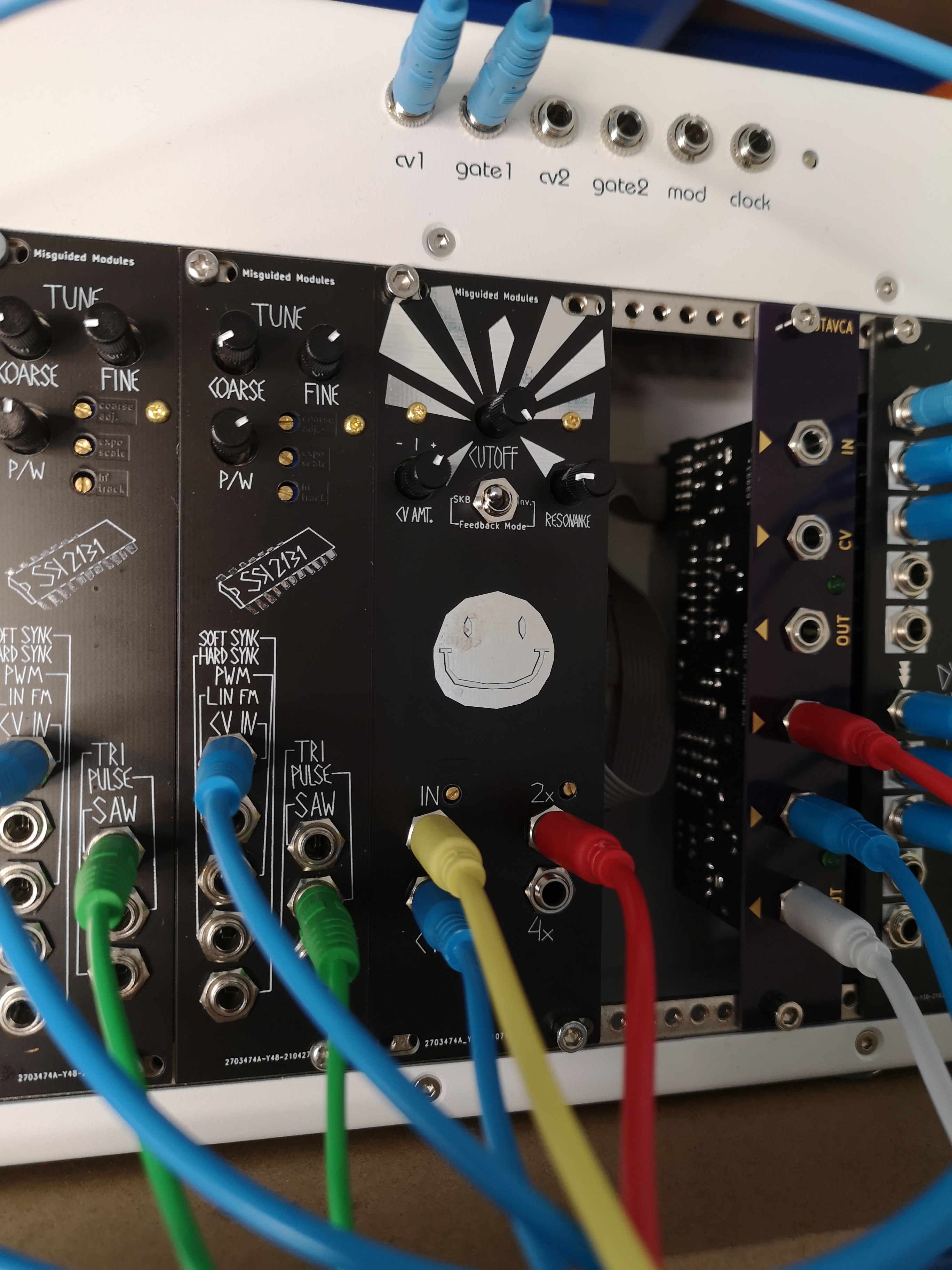
The module
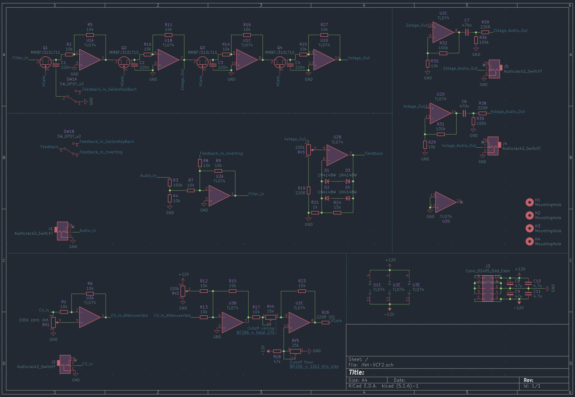
Mx JFET is a low-pass filter with 2- and 4-pole outputs that uses the MMBFJ310L JFET as its variable gain element. It implements both the classic Moog-style inverting feedback path, as well as a more spicy MS20-style Sallen-Key configuration. These can be switched on the fly through the front panel toggle.
There's also an attenuverter on the CV input for, well, attenuating and inverting the control signal. This is useful if you're running this off the same envelope generator but want to attenuate the filter envelope.
The inverting feedback mode is fine - it suffers from the usual problem of high resonance swamping out the input signal, but at more sensible settings it sounds good especially on the 4 pole output.
Where the fun starts is when you flick the switch to the SKB mode, for Sallen-Key-Bach. Much higher resonance levels become practical, and the sound gets much dirtier and in my opinion more interesting. I, uh, got inspired by Aaron Lanterman's lectures on filter design in general and when I saw the lecture on Sallen-Key filters, I decided to incorporate it into Mx JFET immediately. And it turns out that it's fairly easy to switch between SKB mode and Inverting mode:
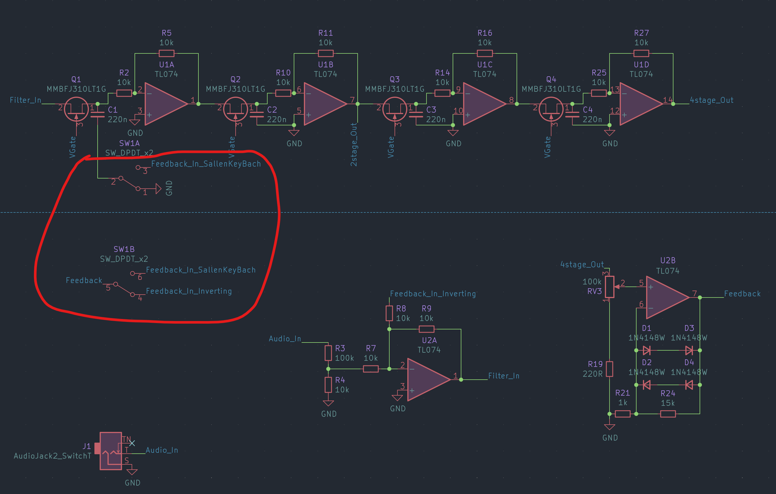
It's just a double pole, double throw switch. In the inverting position, the first capacitor (C1) is grounded, while the feedback is routed to the inverting input of U2A. In the SKB position, feedback is disconnected from U2A and instead it's connected to the normally grounded side of C1.
I think some of the distorted nature of this filter comes from driving the JFETs in a weird way. The particular transistors I'm using are not meant for audio use and I need to use some oddball gate voltages to give them the right behaviour. What I imagine is happening is that it's easy for the cutoff knob to go "past" fully open and into a state where the JFETs saturate more easily, especially if the input is quite hot. To control this behaviour a bit, the module has two tuning pots, which together control the effective range of the cutoff knob.
Design for manufacture
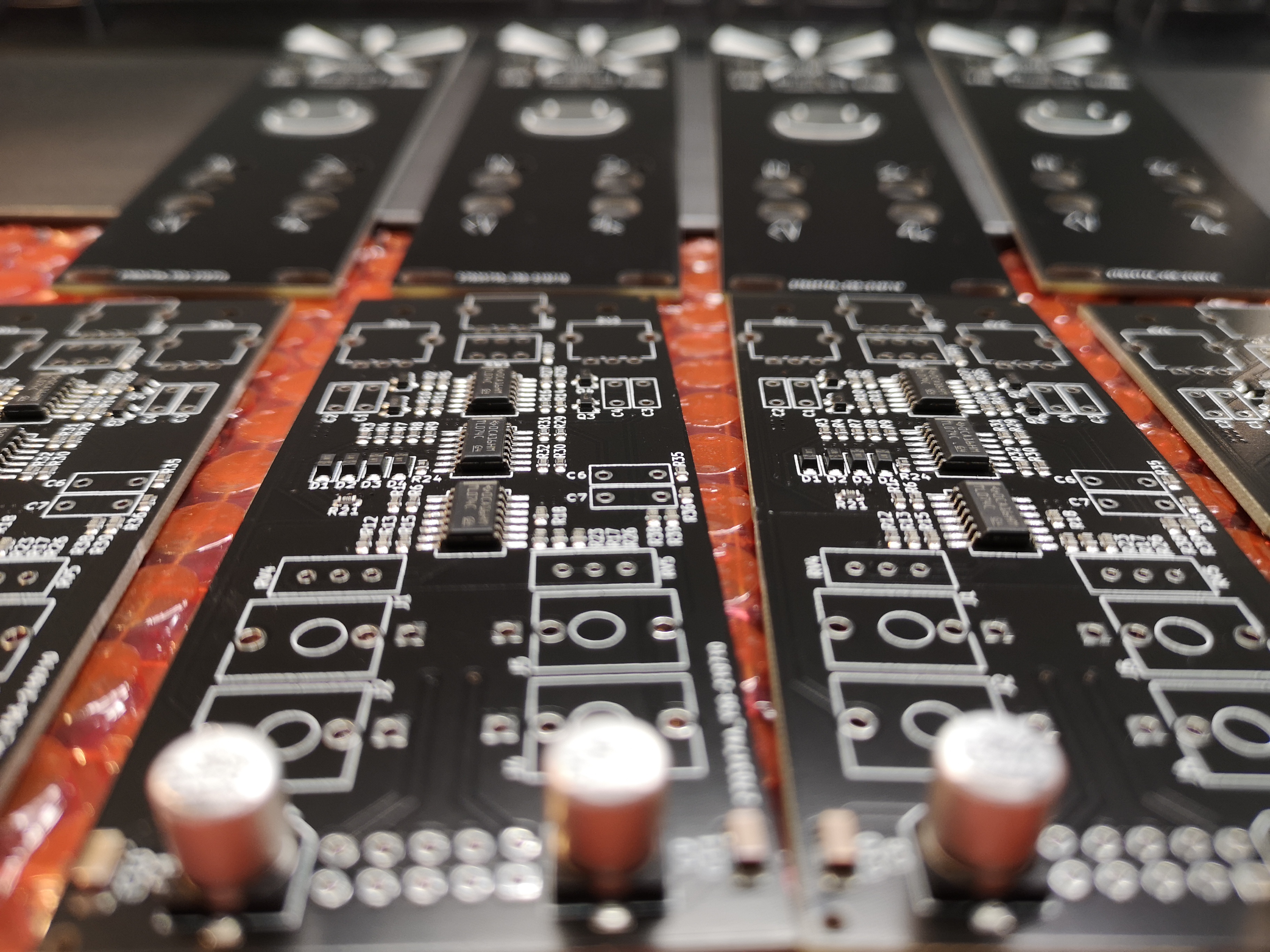
Mx JFET is heavy on SMD components, but all SMD components are populated by my PCB supplier, JLCPCB. There is a handful of components that you need to hand solder yourself (see the BOM below). The panel is made using the same process as the PCB and so overall the design is pretty cheap: I could sell a PCB and panel set for £20 and get a fair margin.
Assembly will take about 40 minutes of soldering/build and maybe 5-10 minutes of tuning.
Most components have fairly obvious placement and orientation. Where you'll need to take care is the trim pots - make sure the screws are towards the sockets and away from the control pots. This is so that they poke through the holes in the panel. I will try to come up with a better build document ahead of a larger scale production run.
BOM
| # | Item | Qty | Source |
|---|---|---|---|
| RV1 | Linear 100k centre detent pot | 1 | Thonk |
| RV2, RV3 | Linear 100k pot | 2 | Thonk |
| RV4, RV5 | 20k/25k trimmer | 2 | Thonk | Rapid |
| C6, C7 | 470nF film capacitor | 2 | Rapid | Ebay |
| C1, C2, C3, C4 | 220nF film capacitor | 4 | Rapid | Ebay |
| J1, J2, J4, J5 | Thonkiconn 3.5mm socket (PJ398SM) + nut (hex or knurled; washer not required) | 4 | Thonk |
| J3 | Power connector - design assumes a keyed connector so no polarity protection! | 1 | Rapid |
| SW1 | DPDT ON-ON Switch | 1 | Thonk |
| M2x10 standoff, M2 nut, M2 screw | 2 | Ebay - I recommend just getting a kit like this one |
Schematic